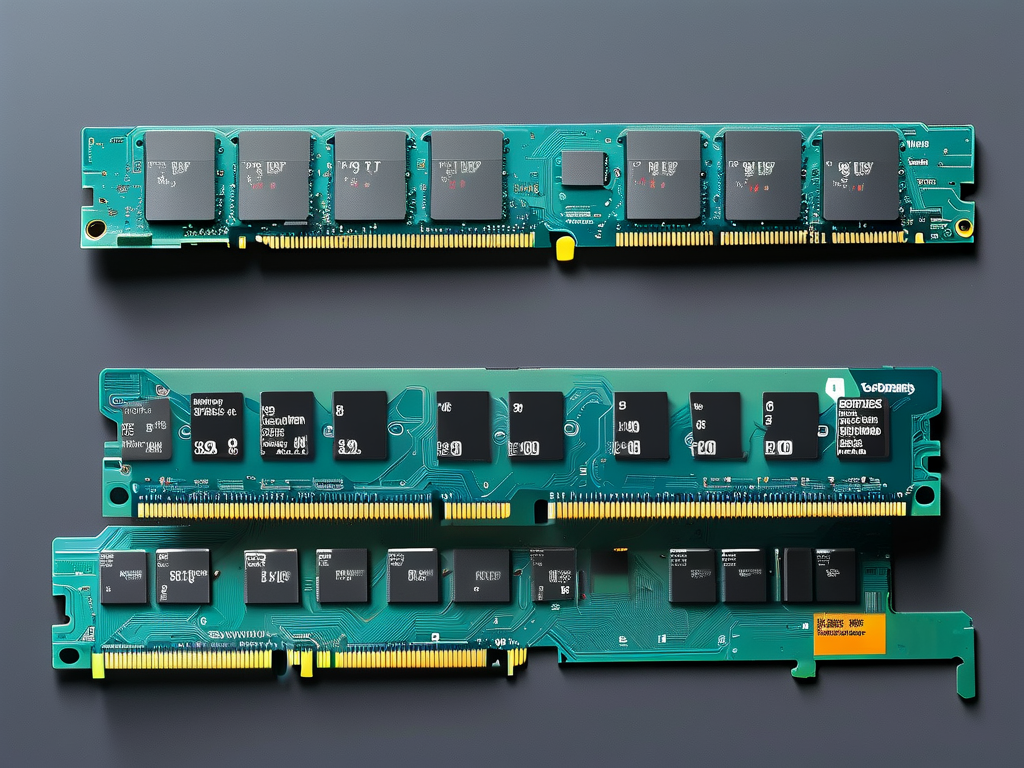
Understanding how to calculate the maximum current draw in memory modules is critical for designing stable electronic systems. This article explores the foundational principles and practical methods for determining peak current values, addressing both theoretical models and real-world variables.

Core Formula for Maximum Current
The primary equation for estimating maximum current in memory devices is derived from Ohm’s Law and power consumption principles:
[ I{max} = \frac{P{max}}{V{dd}} ]
Where ( I{max} ) represents the peak current, ( P{max} ) is the maximum power consumption, and ( V{dd} ) is the operating voltage. For dynamic memory (e.g., DDR4/DDR5), additional factors like refresh cycles and burst operations must be incorporated:
[ I{max} = \frac{P{dynamic} + P{static}}{V{dd}} + I_{leakage} ]
This expanded formula accounts for dynamic power during read/write cycles, static power for idle states, and leakage currents influenced by semiconductor properties.
Critical Parameters in Calculations
- Voltage Fluctuations: Modern memory modules operate at low voltages (1.2V for DDR4, 1.1V for DDR5), making precise voltage measurement essential. Even minor deviations (e.g., ±3%) can alter current calculations by 15-20%.
- Operational Frequency: Higher clock speeds increase switching activity, directly impacting dynamic power. A DDR5 module at 6400 MT/s may require 22% more current than a 4800 MT/s counterpart under identical workloads.
- Temperature Coefficients: Leakage currents double approximately every 10°C temperature rise. Designers must account for worst-case thermal scenarios:
def leakage_adjustment(base_current, temp_diff):
    return base_current * (2 ** (temp_diff / 10))
Practical Implementation Challenges
While formulas provide theoretical guidance, physical prototypes often reveal discrepancies due to:
- PCB Trace Resistance: A 50mm copper trace with 0.5mm width adds ~0.07Ω resistance, creating voltage drops that affect current measurements.
- Simultaneous Switching Noise: When multiple memory chips activate concurrently, transient current spikes can exceed calculated maxima by 30-40%.
- Manufacturing Tolerances: Semiconductor process variations (±8% threshold voltage differences between batches) necessitate safety margins in designs.
Validation and Measurement Techniques
Accurate verification requires both simulation tools and physical testing:
- SPICE Modeling: Circuit simulations predict current profiles across operational modes.
- Oscilloscope Current Probing: High-bandwidth differential probes capture microsecond-scale current transients.
- Thermal Imaging: Identifies localized hot spots indicating current crowding.
A typical validation workflow might include:
=AVERAGE(B2:B100) + 3*STDEV(B2:B100) // Statistical peak estimation
Industry Standards and Safety Margins
JEDEC specifications recommend designing power delivery networks (PDNs) to handle 125% of calculated ( I_{max} ). For mission-critical systems, some manufacturers implement 150% derating factors. Recent studies show that incorporating machine learning predictions for usage patterns can reduce safety margins to 110% while maintaining reliability.
Emerging Memory Technologies
New non-volatile memory types like MRAM and ReRAM introduce different current characteristics. Their bidirectional current flows and asymmetric write/read profiles require modified calculation approaches:
[ I{max_nv} = \sqrt{\frac{P{write}}{R{cell}}} ]
Where ( R{cell} ) denotes the memristor's resistance state.
Calculating memory maximum current remains a blend of physics-based modeling and empirical adjustment. As memory architectures evolve, engineers must continuously adapt their calculation methodologies while maintaining rigorous validation protocols. By combining theoretical formulas with real-world testing and emerging predictive analytics, designers can optimize power systems for both efficiency and reliability.


