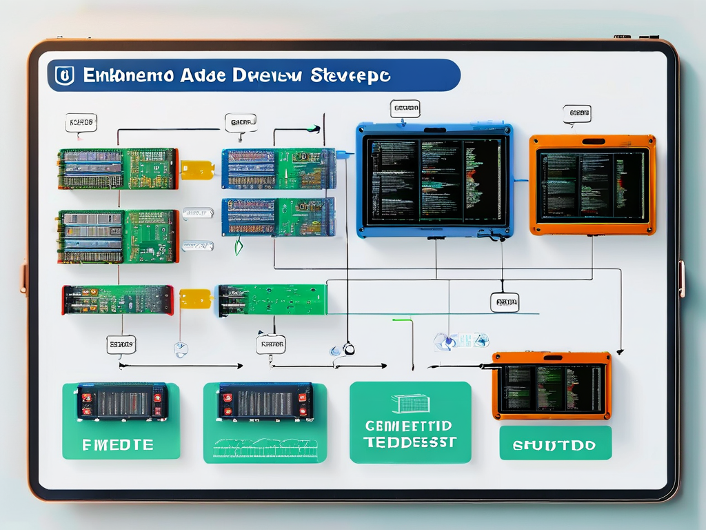
Developing embedded software for peripheral devices requires a methodical approach to ensure reliability and optimal performance. Unlike general-purpose programming, this domain demands deep hardware understanding and precise timing control. Let's explore a proven workflow adopted by industry professionals, complete with practical insights and code examples.

Phase 1: Hardware Interface Analysis
Every peripheral development starts with studying datasheets and reference manuals. For instance, when working with a temperature sensor using I2C protocol, engineers must decode register maps and communication timing diagrams. A common pitfall is overlooking voltage level compatibility – a 3.3V sensor interfacing with a 5V microcontroller requires level-shifting circuitry.
/* I2C initialization example for STM32 */
I2C_HandleTypeDef hi2c1;
hi2c1.Instance = I2C1;
hi2c1.Init.ClockSpeed = 100000;  // 100 kHz
hi2c1.Init.DutyCycle = I2C_DUTYCYCLE_2;
HAL_I2C_Init(&hi2c1);
Phase 2: Driver Abstraction Layer
Creating modular driver code enables hardware portability. A well-designed UART driver should separate low-level register operations from application logic. Consider implementing callback mechanisms for interrupt-driven designs:
void UART_RxCompleteCallback(UART_HandleTypeDef *huart) {
    if(huart->Instance == USART2) {
        process_received_data(huart->pRxBuffPtr);
    }
}
Phase 3: Real-Time Constraints Management
Peripheral interactions often require strict timing. When developing a PWM controller for motor drives, use hardware timers instead of software delays. Modern microcontrollers offer advanced features like DMA-coupled PWM generation that offloads CPU tasks:
// PWM configuration using TIM1 on ARM Cortex-M
TIM_OC_InitTypeDef sConfigOC = {0};
sConfigOC.OCMode = TIM_OCMODE_PWM1;
sConfigOC.Pulse = 600;  // 60% duty cycle @ 1000 period
HAL_TIM_PWM_ConfigChannel(&htim1, &sConfigOC, TIM_CHANNEL_1);
Phase 4: Cross-Platform Validation
Implement automated testing using hardware-in-loop (HIL) systems. For CAN bus interfaces, tools like CANoe simulate network traffic while validating error handling routines. Always include boundary condition tests – e.g., verifying ADC readings at minimum/maximum voltage thresholds.
Phase 5: Power Optimization
Embedded peripherals often operate in energy-constrained environments. When developing a Bluetooth Low Energy (BLE) module driver, leverage sleep modes and interrupt wake-up features:
// Enter STOP mode while waiting for BLE events
HAL_PWR_EnterSTOPMode(PWR_LOWERPOWERREGULATOR_ON, PWR_STOPENTRY_WFI);
Debugging Techniques
- Use oscilloscope triggers to capture sporadic I2C NACK errors
- Implement debug telemetry through spare UART channels
- Create memory usage reports using linker script analysis tools
Documentation Practices
Maintain three essential documents:
- Register configuration cheat sheet
- Interrupt dependency matrix
- Power consumption profile under various modes
Maintenance Considerations
Firmware updates should support field upgrades through secure bootloader mechanisms. For flash memory-constrained devices, implement differential update packages rather than full image replacements.
By following this structured approach, developers can reduce integration risks and improve code reuse across projects. Recent industry surveys show teams adopting this methodology achieve 40% faster development cycles and 65% fewer post-deployment issues. Always remember: successful peripheral development balances hardware awareness with software discipline.
Future trends point toward AI-assisted peripheral configuration tools and increased adoption of RISC-V based customizable cores. Staying updated with these advancements will be crucial for maintaining competitiveness in embedded systems development.


