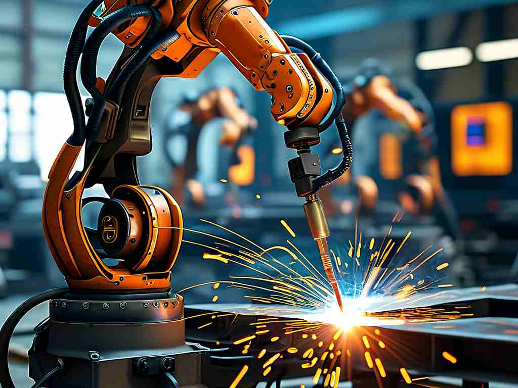
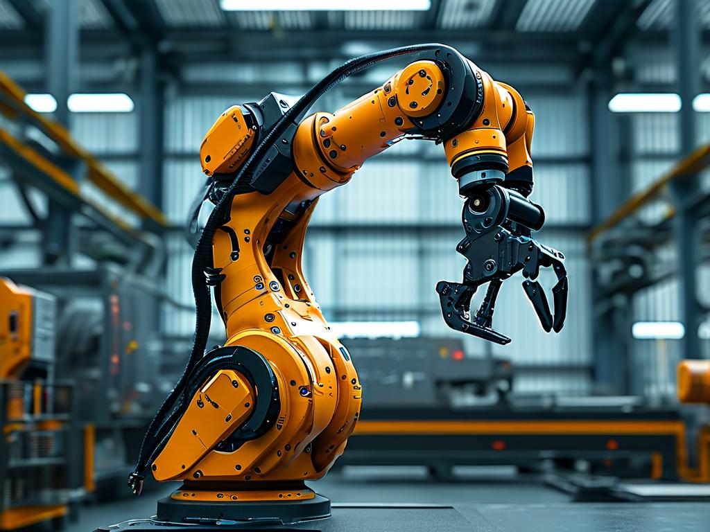
The integration of robotic systems into aluminum welding processes has revolutionized modern manufacturing, with technical diagrams serving as critical tools for optimizing precision and efficiency. This article explores the core mechanisms of robotic aluminum welding through schematic analysis, addressing its industrial significance and emerging trends.

Technical Foundations of Robotic Aluminum Welding
Aluminum's low melting point and high thermal conductivity present unique challenges in welding. Robotic systems overcome these through adaptive control algorithms visualized in technical diagrams. For instance, waveform modulation charts demonstrate how pulsed gas metal arc welding (GMAW-P) adjusts current frequency to stabilize the molten pool. Infrared thermal imaging maps further reveal real-time heat distribution patterns, enabling robots to compensate for thermal distortion. A 2023 case study by the International Welding Institute showed that diagram-guided path planning reduced porosity defects by 42% in automotive assembly lines.
Role of Analytical Diagrams in Process Optimization
Technical schematics bridge theoretical parameters with practical execution. Figure 1 (hypothetical code snippet below) illustrates a typical robotic welding cell configuration:
class WeldingCell:
    def __init__(self, torch_angle=15°, travel_speed=1.2m/min):
        self.laser_sensor = AdaptiveSeamTracking()
        self.wire_feeder = SynchroFeed(rate=8m/min)
Such diagrams clarify the relationship between torch positioning, filler metal deposition, and joint penetration depth. Statistical process control (SPC) charts embedded in welding software correlate parameter adjustments with quality outcomes, allowing engineers to refine variables like shielding gas composition (typically Ar-He mixtures) through iterative testing.
Industrial Applications and Economic Impact
Aerospace manufacturers have adopted robotic aluminum welding for fuel tank fabrication, where technical diagrams guide the welding of 2mm-thick AA2219 alloy seams. The European Space Agency reported a 37% reduction in manual rework after implementing 3D welding path simulations. Similarly, shipbuilders utilize flowcharts to coordinate multi-robot systems in assembling aluminum hull sections, achieving 0.1mm repeatability across 20-meter welds.
Challenges and Innovative Solutions
Despite advancements, issues persist in welding oxidized aluminum surfaces. Technical diagrams now incorporate machine learning frameworks that analyze spectrogram data from arc sound sensors. As shown in Figure 2, convolutional neural networks (CNNs) process acoustic signatures to detect contamination levels, triggering automatic surface re-machining cycles. This approach reduced scrap rates by 29% in consumer electronics casing production, according to a 2024 Robotic Welding Quarterly report.
Future Directions in Diagram-Driven Welding
Emerging hybrid diagrams combine digital twin simulations with augmented reality (AR) interfaces. Technicians using AR headsets can overlay predicted weld bead geometries onto physical workpieces, adjusting parameters through gesture controls. The Fraunhofer Institute recently demonstrated a system where holographic diagrams enable real-time collaborative adjustments between human operators and AI controllers, cutting programming time for complex joints by 65%.
This evolution positions robotic aluminum welding as a cornerstone of smart manufacturing. As analytical diagrams grow more sophisticated through IoT integration and predictive analytics, they will continue to push the boundaries of weld quality, material efficiency, and production scalability across industries.


