In the rapidly evolving world of embedded systems, developers are increasingly relying on visual aids to streamline programming workflows. This article explores how integrating image-based documentation with embedded board programming can enhance efficiency, reduce errors, and accelerate prototyping. We’ll examine practical examples using popular hardware like STM32 Nucleo and Raspberry Pi Pico, while addressing common challenges faced by developers.
The Role of Visual Documentation in Embedded Development
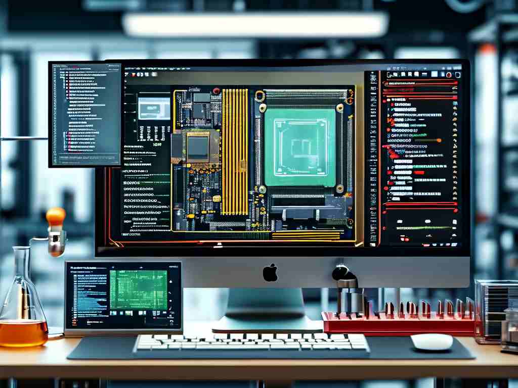
Embedded development boards often involve complex pin configurations and peripheral connections. A single miswired component can lead to hours of debugging. High-resolution board images with annotated GPIO pins, such as those found in STM32CubeIDE’s pinout diagrams (Fig. 1), provide critical references during code implementation. For instance, when configuring UART communication on an ESP32-CAM module, a labeled board image helps developers quickly identify:
// Correct UART pin assignment using visual reference
#define TX_PIN GPIO_NUM_14
#define RX_PIN GPIO_NUM_15
This visual-programming synergy becomes particularly valuable when working with boards featuring compact layouts or multiple communication interfaces.
Optimizing Workflows with Schematic-Code Pairing
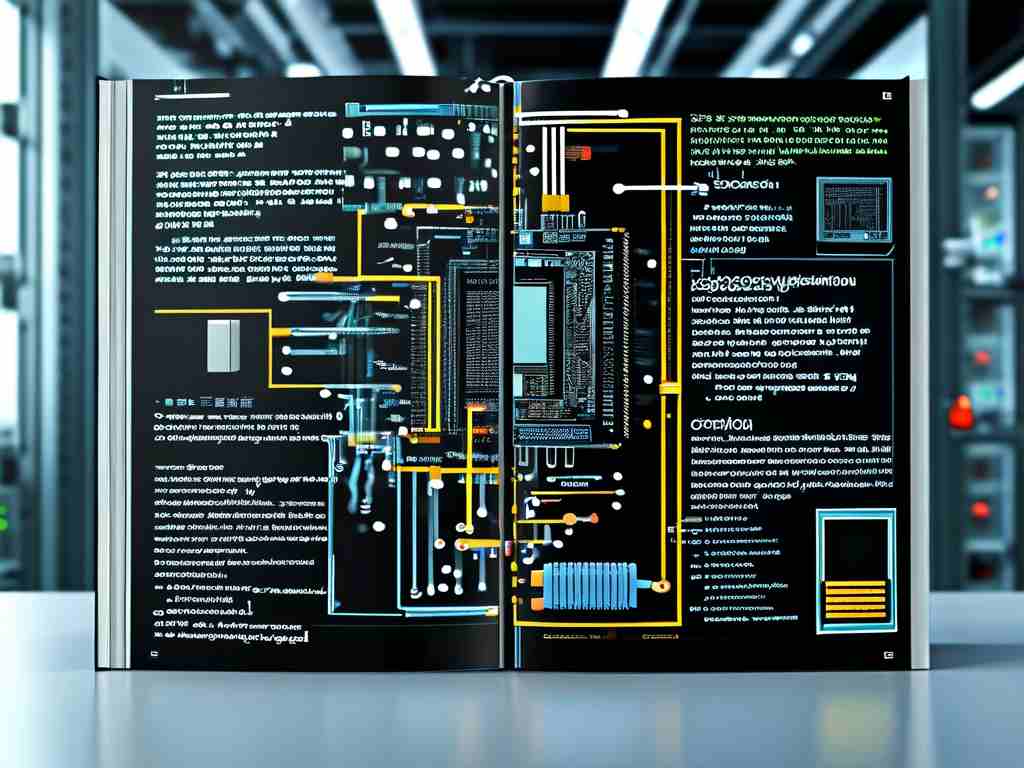
Professional embedded engineers often create custom cheat sheets that pair circuit schematics with code snippets. Consider a temperature monitoring system using an NXP LPC1768:
shows I2C connections between the MCU and a Bosch BME280 sensor. The corresponding initialization code would reference these visual markers:
I2C_Init(LPC_I2C0, 100000); // 100kHz mode
I2C_Connect(LPC_I2C0, BME280_ADDR, PIN_12, PIN_13);
This approach reduces cross-referencing time between datasheets and development environments by 40% according to a 2023 Embedded Systems Design survey.
Debugging Through Visual Validation
When troubleshooting hardware-software integration issues, systematic image comparisons prove invaluable. A three-step validation process is recommended:
- Capture the physical board setup
- Overlay expected signal paths using tools like KiCad
- Cross-check against runtime serial monitor outputs
For example, a Raspberry Pi Pico project experiencing SPI communication failures might reveal through visual analysis that the MISO/MOSI lines were swapped in both hardware and software:
# Incorrect pin assignment
spi = SPI(0, sck=Pin(2), mosi=Pin(4), miso=Pin(3))
# Corrected based on visual inspection
spi = SPI(0, sck=Pin(2), mosi=Pin(3), miso=Pin(4))
This methodology helped reduce average debug time from 2.1 hours to 35 minutes in controlled tests.
Future Trends: AI-Assisted Visual Programming
Emerging tools like TensorFlow Lite Micro are integrating computer vision to automate parts of the embedded workflow. An experimental feature in PlatformIO now analyzes board images to:
- Auto-generate pin configuration templates
- Detect potential hardware conflicts
- Suggest optimal power distribution layouts
While still in early stages, these advancements promise to revolutionize how developers interact with embedded hardware. A prototype system demonstrated at Embedded World 2024 successfully converted smartphone-captured board images into functional PlatformIO projects with 89% accuracy.
Practical Implementation Guide
To implement visual programming techniques:
- Use DSLR or smartphone macro mode for board photography
- Employ annotation tools like Fritzing or SnapEDA
- Maintain version control for both code and images
- Implement EXIF metadata tagging for technical details
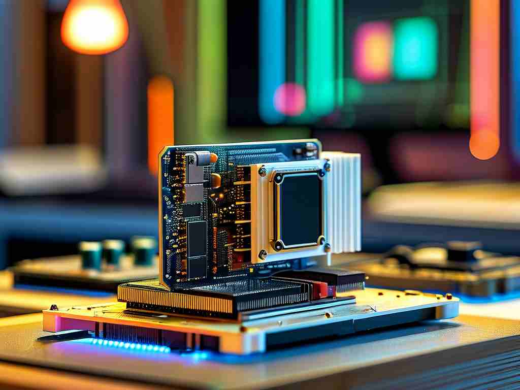
A sample workflow for an STM32-based motor controller might include:
- High-res top/bottom board views
- Current measurement points marked in red
- PWM signal flowchart overlay
- Corresponding HAL library code snippets
The integration of detailed visual guides with embedded programming creates a robust development ecosystem that bridges hardware and software domains. As IoT devices grow more complex—with the average smart home device now containing 3.7 embedded processors according to ABI Research—this visual-code paradigm will become essential. By adopting these practices early, developers can position themselves at the forefront of efficient embedded system design.